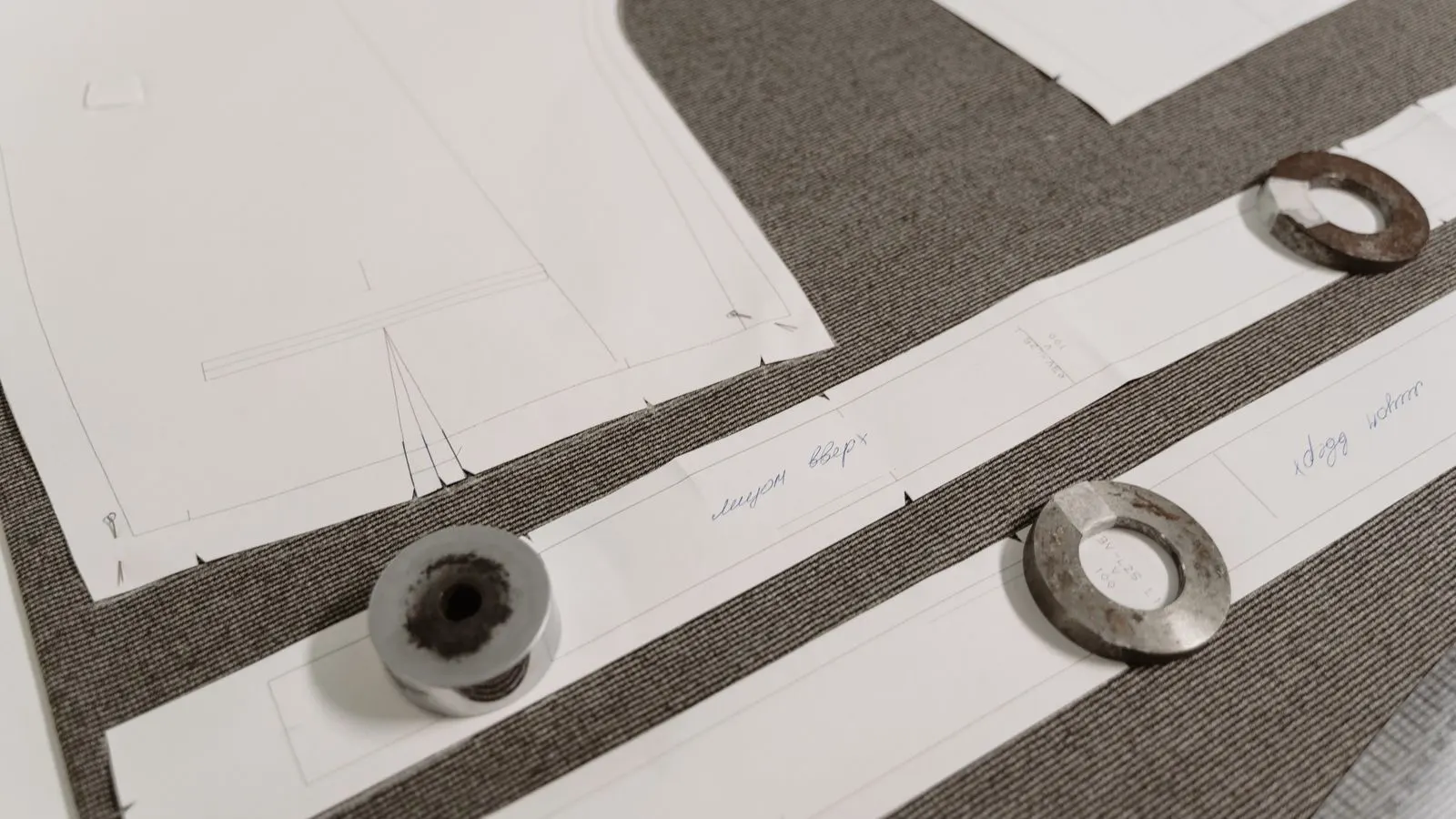
How to Design a Robust Progressive Die Layout
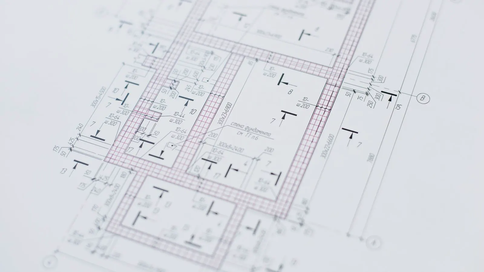
Design a robust progressive die by mapping material flow from raw stock to finished part. Use defined station sequences, adequate clearance, and proper support to prevent binding, bending, and springback. Verify the layout with a dry run and trial parts before full production.
- Map the full material flow before selecting punch sizes or station counts.
- Space stations to prevent sheet curl, binding, and part-to-part interference.
- Verify the layout with a dry run and trial parts before full production.
- Check springback and bend direction early to avoid secondary operations.
- Review clearance, support, and lubrication points after each design revision.
Define the Material Flow Path Before Choosing Station Count
Start with the part drawing and raw stock specifications. Identify the starting point, bend direction, punch sequence, and final part orientation. A progressive die moves material through a series of stations. Each station performs one or more operations. The layout must keep the material moving smoothly from one station to the next.
Write down the following:
- Raw stock material, thickness, and width.
- Final part shape and critical dimensions.
- Bend direction and bend height for each bend.
- Punch, trim, and form sequence.
- Part-to-part clearance between finished pieces.
This list becomes the foundation for every layout decision. If the flow is unclear, the die will bind, curl, or produce scrap. Do not select punch sizes before you understand where the sheet is going.
Choose the Operation Sequence That Matches the Part Geometry
Not every part requires the same station order. A flat part with a single bend may need a punch, form, and trim sequence. A complex bracket may require multiple bends, a flange, and a final trim. The sequence must respect the material behavior.
Consider the following order:
- Form operations that create the main shape.
- Bends that create the final angles.
- Trims that remove excess material.
- Any secondary operations such as notching, embossing, or deburring.
The reason for this order is to avoid interfering with already-formed features. A trim punch placed before a bend can cut into the bend zone and damage the part. A form station placed after a trim may pull material unevenly and cause springback.
Use the part drawing to identify which features are primary and which are secondary. Primary features define the part. Secondary features support those primary features. The die layout should protect the primary features first.
Space Stations to Prevent Binding and Sheet Curl
Station spacing is one of the most common causes of progressive die failure. If stations are too close, the sheet curls between them. If stations are too far apart, the sheet may drift, bind, or tear. The spacing must match the material thickness and the bend height.
Use the following general rules:
| Station Type | Typical Spacing Consideration | Reason |
|---|---|---|
| Punch and form | Keep form punches close to the next bend station | Reduces sheet curl and bending distortion |
| Trim and punch | Leave enough clearance for the trim blade to pass without hitting the formed part | Prevents blade contact and part damage |
| Multiple bends | Space bends to avoid overlapping bend zones | Prevents material thinning and cracking |
| Final trim and eject | Keep trim clear of the ejector path | Prevents part interference and scrap |
The exact spacing depends on the material, thickness, and bend height. A thin sheet may need more spacing to prevent curl. A thick sheet may need more support to prevent bending at unintended points.
When in doubt, add a small gap between stations. A little extra space is easier to adjust than a binding die. Do not rely on the press to hold the sheet in place. The die itself must control the material flow.
Plan for Springback and Bend Direction
Springback is the tendency of the sheet to spring back after bending. If you ignore it, the part will not meet tolerance. The die design must account for springback in every bend station.
Check the following:
- Bend direction relative to the grain direction.
- Bend height and bend radius.
- Material thickness and yield strength.
- Whether the bend is inside or outside the part profile.
The reason for this check is to set the correct punch and die angle. If the punch angle is too shallow, the part will spring back more than expected. If the punch angle is too steep, the material may crack or thin.
For parts with multiple bends, the bend direction must be consistent. A part that bends in one direction at station two and the opposite direction at station four will be difficult to hold in the die. The layout should group bends in the same direction where possible.
If the part drawing shows tight tolerance on bend angles, add a note to the die design. The tooling design team may need to adjust the punch angle or add a forming station to control the bend.
Support the Material at Every Station
A progressive die must support the sheet at every station. Without support, the sheet will vibrate, drift, or bind. The support structure includes guides, back plates, and punch holders.
Use the following support points:
- Entry guides at the first station.
- Centering guides at each form or punch station.
- Back plate support at trim stations.
- Punch holder clearance at all stations.
The reason for these supports is to keep the material aligned. A misaligned sheet will hit a punch at the wrong angle. A punch that hits at an angle will wear quickly and produce poor part quality.
Check the clearance between the punch and the die. The clearance must be small enough to cut cleanly but large enough to prevent binding. A clearance that is too tight will cause the punch to drag. A clearance that is too loose will cause a rough cut and burrs.
Review the clearance with the tooling design team. They will set the final value based on the material and the press. Do not guess the clearance. A wrong value will cause scrap and tool wear.
Verify the Layout With a Dry Run and Trial Parts
The final step is to verify the layout before the die is cut. A dry run uses a blank material and checks the flow without cutting. It shows whether the sheet moves smoothly through each station.
Perform the following checks:
- Feed the blank into the first station.
- Watch the sheet as it moves to the second station.
- Check for curl, binding, or drift.
- Repeat the dry run with the full part shape.
The reason for this check is to catch layout errors before the tooling is cut. A dry run is inexpensive. A failed first trial is not.
After the dry run, produce trial parts. Inspect the parts for the following:
- Bend angle accuracy.
- Punch hole size and position.
- Trim edge quality.
- Springback at each bend.
- Part-to-part clearance.
If the trial parts show errors, adjust the layout and run another dry run. Do not cut the final tooling until the trial parts meet tolerance. A small adjustment in the dry run can save a full tooling revision.
Common Mistakes That Break a Progressive Die Layout
Many progressive dies fail because of a few repeated mistakes. Avoid these:
- No material flow map. The tooling team guesses the sequence instead of using a defined flow.
- Stations too close. The sheet curls and binds between stations.
- No springback check. The bend angle is off and the part fails tolerance.
- Clearance guessed. The punch drags or the cut is rough.
- No dry run. The first trial produces scrap and the die is reworked.
Each of these mistakes is avoidable. A clear flow map, proper spacing, and a dry run catch most problems before they become expensive. The die design should be a controlled process. It should not be a series of guesses.
Final Verification Checklist
Before the die is cut, confirm the following:
- The material flow map is complete and approved.
- The station sequence matches the part geometry.
- Station spacing allows for sheet curl and drift.
- Springback is accounted for at every bend.
- Support points are defined at every station.
- Punch and die clearance is set.
- A dry run has been performed.
- Trial parts meet tolerance.
Use this checklist as a gate. Do not proceed to tooling production until every item is checked. A robust progressive die is not a single step. It is a series of controlled decisions. Each decision must support the next. When the layout is verified, the die will perform as expected.
Frequently asked questions
How do I know if my station spacing is correct?
Run a dry run with a blank material. If the sheet curls, binds, or drifts, the spacing is wrong. Adjust the spacing and repeat the dry run.
Can I change the operation sequence after the die is cut?
No. The sequence is built into the die. Changing it requires rework and can damage the tooling. Define the sequence before the die is cut.
What clearance should I use for thin sheet?
Use a smaller clearance for thin sheet to avoid burrs and rough cuts. The exact value depends on the material and thickness. Review the clearance with the tooling design team.
How do I control springback in a progressive die?
Set the punch angle to compensate for springback. Check the bend angle after each trial and adjust the punch angle if needed. A dry run helps identify where springback occurs.
Do I need a dry run for every die?
Yes. A dry run catches layout errors before the tooling is cut. It is a low-cost check that prevents expensive rework and scrap.